Arduinos are a great tool for learning electronics, so why not take it one step further and build your own Arduino based board.
Parts list
- Either an ATMEGA168 or an ATMEGA328
- 2x 22pF capacitors
- 1x 16Mhz crystal
- 1x 100uF capacitor (for burning the bootloader and uploading sketches)
- Either breadboard or prototype board
- Link wires
- An Arduino or compatible board (chicken or the egg situation)
The above list is the bare minimum, you may also wish to add:
- An LED from (ATMEGA) pin 19 to +ve via a 220Ω resistor
- A reset switch between (ATMEGA) pin 1 and ground. If doing so also add a 10kΩ resistor between (ATMEGA) pin 1 and +ve
- A 5v power supply to take your new Arduino compatible away from your computer.
Building the Arduino clone
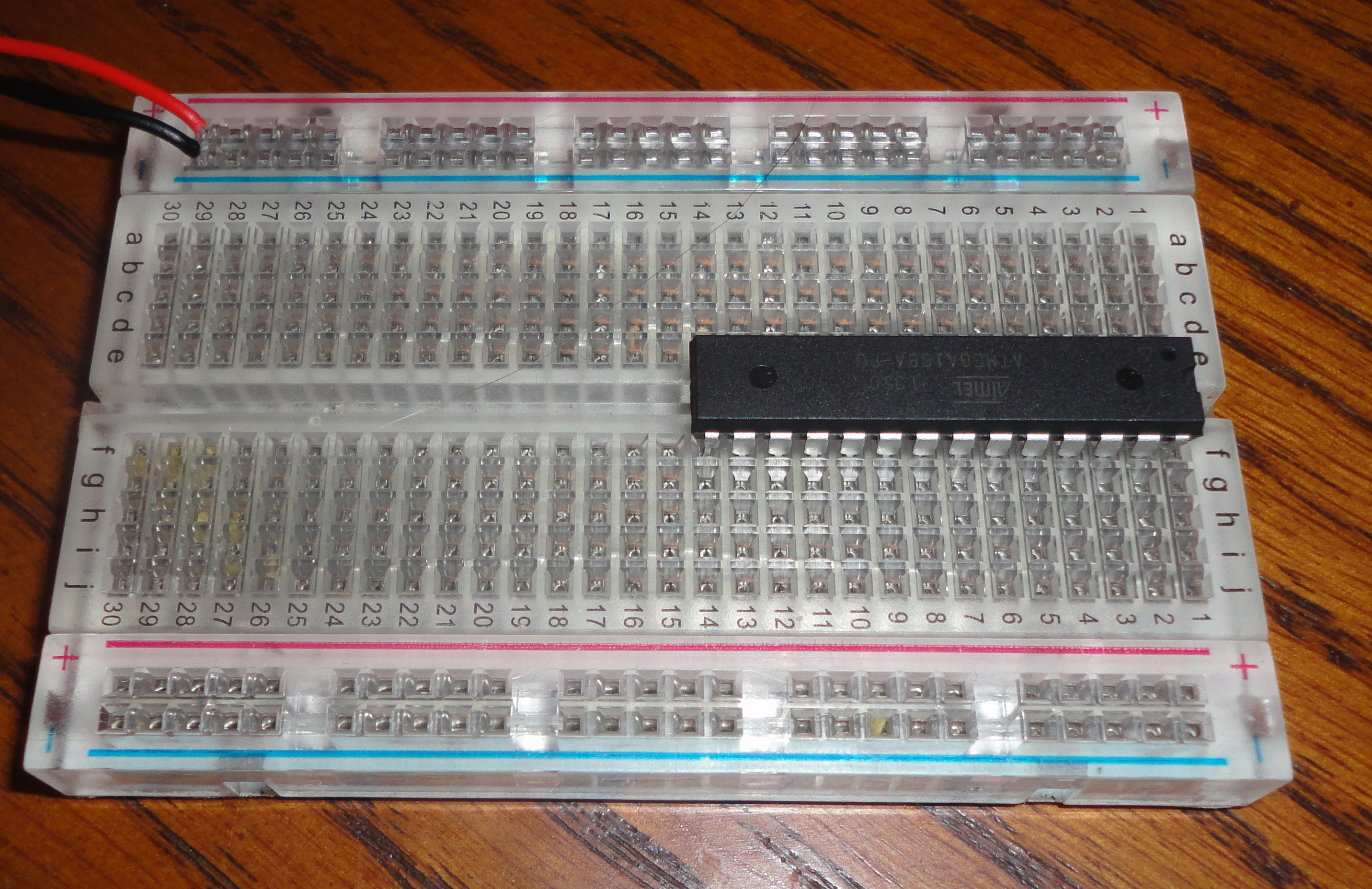
First of all plug your ATMEGA chip into the breadboard, with the centre of the chip running over the small gap in the board. Ideally placing the end of the chip with a semi-circular notch on it to the end of the breadboard.
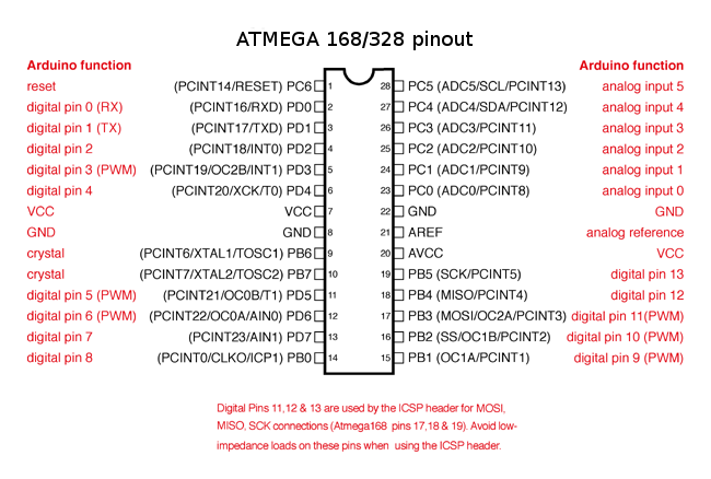
Before going any further I will add a copy of the ATMEGA pinout also showing the associated Arduino pins as they do differ.
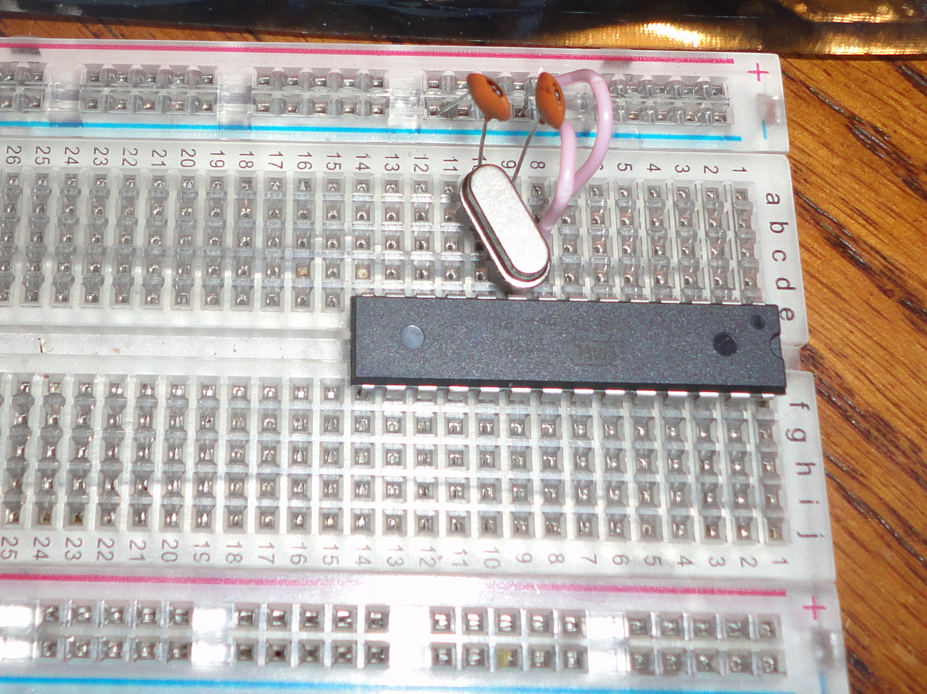
Connect the 16Mhz crystal between (ATMEGA) pins 9 and 10, also adding a 22pF capacitor between (ATMEGA) pin 9 and ground, then between (ATMEGA) pin 10 and ground.
Finally, using jumper wire, connect (ATMEGA) pin 7 to the +ve (red) power rail and (ATMEGA) pin 8 to the ground (black) power rail.
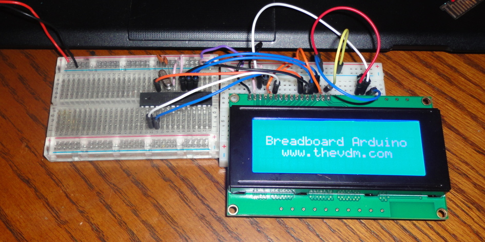
You should now have something that looks a little like this:
Effectively that is now an Arduino clone, simple isn’t it. Well not quite, in order for it to be an Arduino clone the ATMEGA chip requires the bootloader burning to it.
Preparing your existing Arduino
With the method used in this tutorial (at present) an Arduino board is required to act as an ISP (In-System Programmer) in order to program the ATMEGA chip.
Connect an Arduino to your computer using a USB cable then open the Arduino software, ensure that the correct Arduino board is selected under [Tools -> Board] and the correct serial port is selected under [Tools -> Serial Port].
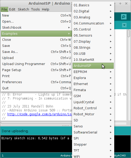
Open the ArduinoISP sketch [File -> Examples -> ArduinoISP]
The ArduinoISP sketch allows you to use an existing Arduino to program an external chip, upload the sketch to your Arduino by clicking the ‘Upload’ button or [File -> Upload]
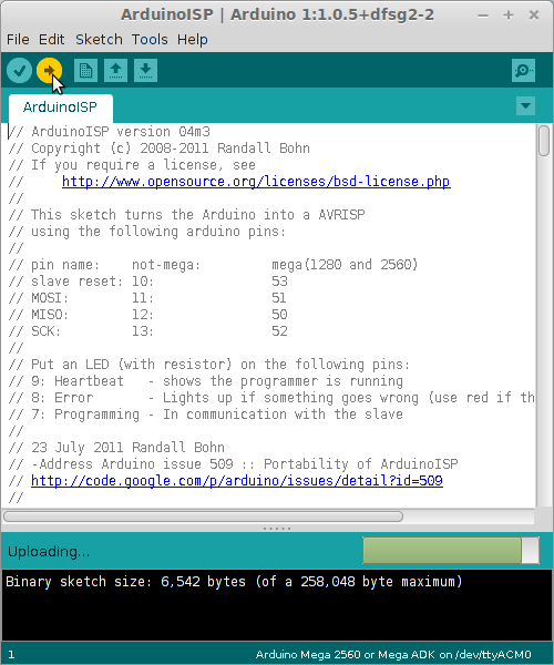
The upload will take a short moment to complete, once done your existing Arduino is ready to be wired up to the ATMEGA chip for programming.
Connecting the Arduino to the ATMEGA
In order to program the ATMEGA chip from the Arduino 6 wires will be used to link them together including +ve and ground, a 100uF capacitor will also be used to prevent your Arduino from resetting.
Connect your ATMEGA chip to your Arduino following the connections in the table below, the left column relates to the ATMEGA chip pins, the middle column is to be followed if using an Arduino board (other than the Mega2560) and the right column is to be followed if using an Arduino Mega2560.
| ATMEGA | Arduino | Arduino Mega2560 |
| Pin 1 (Reset) | Digital 10 | Digital 53 |
| Pin 17 (MOSI) | Digital 11 | Digital 51 |
| Pin 18 (MISO) | Digital 12 | Digital 50 |
| Pin 19 (SCK) | Digital 13 | Digital 52 |
| Pin 7 (VCC) | 5V | 5V |
| Pin 8 (GND) | GND | GND |
Finally add the 100uF capacitor between the Arduinos 5V and Reset pins, the pin on the side with the silver strip should be inserted into the reset pin.
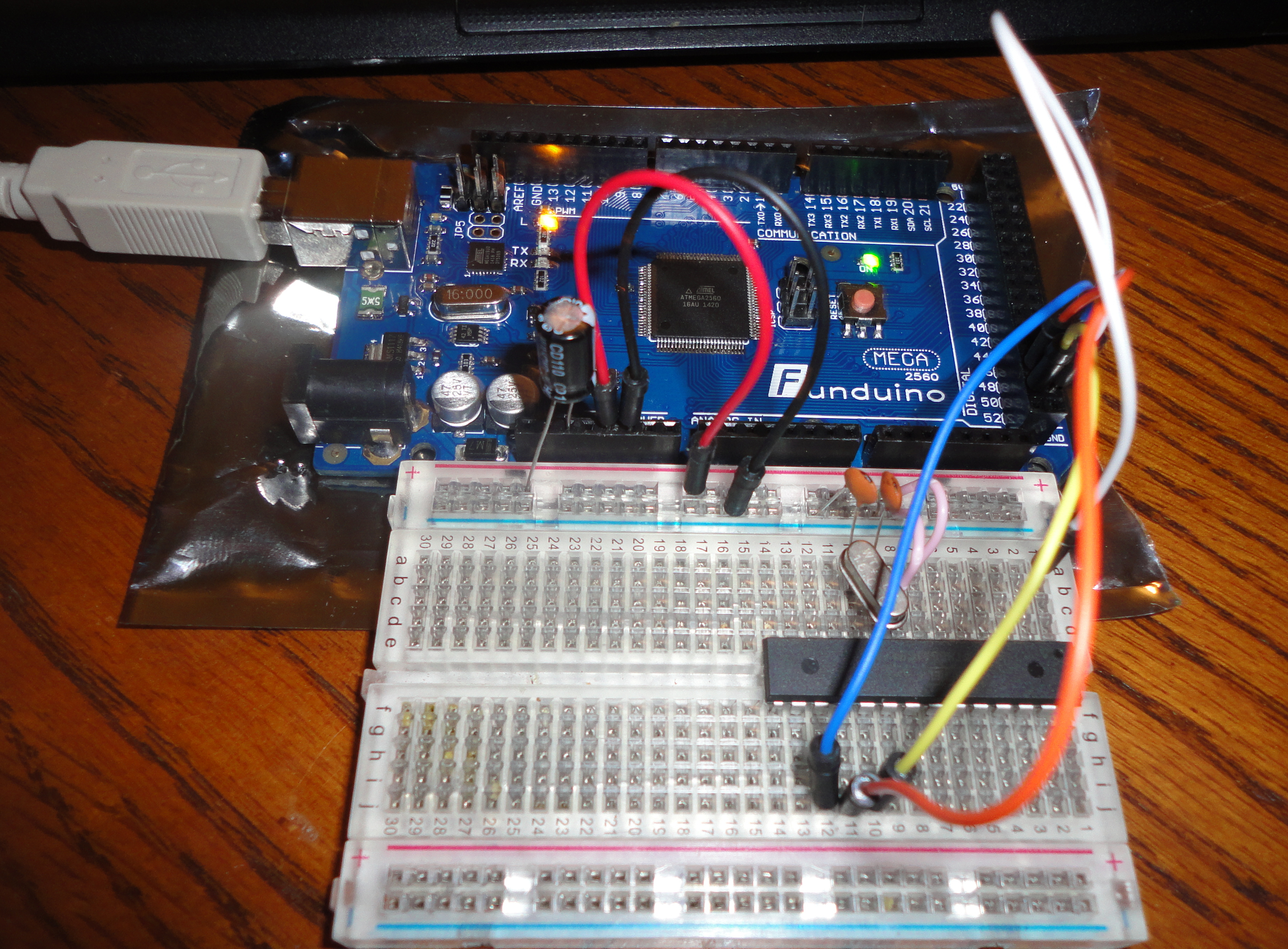
If you’re using an Arduino (or Funduino in my case) Mega2560 your setup should look like the following image, if you are using a different Arduino board it will look a little different:
Burning the bootloader
Now that the ATMEGA is connected to the Arduino board it is time to burn the bootloader to the ATMEGA chip.
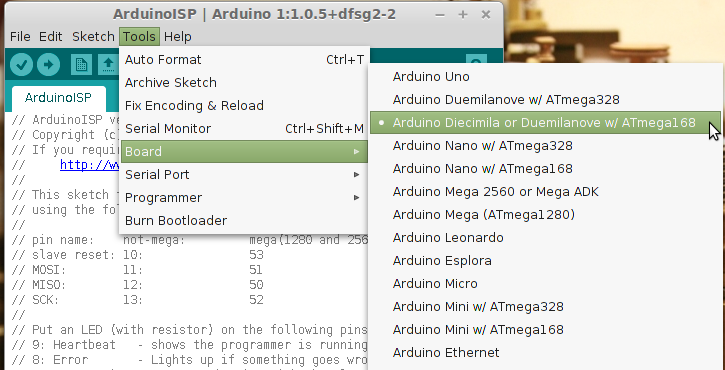
If you closed the Arduino software from earlier then re-open it. Under [Tools -> Board ->] select either ‘Arduino Duemilanove w/ ATmega328‘ or ‘Arduino Diecimila or Duemilanove w/ ATmega168‘ depending on whether you are using an ATMEGA328 or ATMEGA168.
After selecting the board appropriate for your ATMEGA chip ensure that the 2 boards are correctly wired together and that the 100uF capacitor is in place.
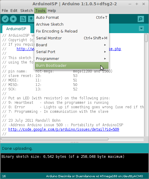
To burn the bootloader to the ATMEGA chip select [Tools -> Burn Bootloader], this process should take no longer than a minute. If you receive an error while burning the bootloader double check all the wiring, I also found that unplugging the USB cable from the computer to Arduino and re-connecting it solved the burn issue.
Now that the bootloader has been burnt to the ATMEGA chip, you effectively have a very basic Arduino clone.
Uploading sketches to the ATMEGA
When uploading sketches to the ATMEGA chip you will need to connect the chip up to your Arduino as described above, making sure the 100uF capacitor is in place. The Arduino board will also need to have the ArduinoISP sketch uploaded to it.
As uploading sketches is a very broad subject with the infinite possible programs I will use the LED Blink sketch as bundled with the Arduino software.
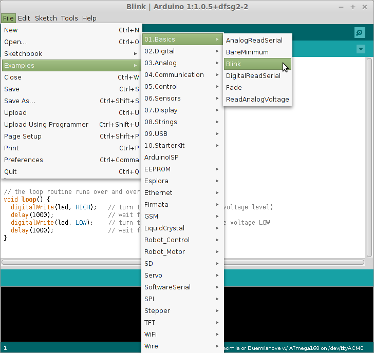
Select [File -> Examples -> 01.Basics -> Blink] to load the LED Blink sketch.
As mentioned at the top of the Blink sketch ‘Pin 13 has an LED connected on most Arduino boards.’, although our ATMEGA chip doesn’t have an LED attached yet, remember that pin 13 is referring to the Arduino pin, not the ATMEGA pin.
Arduino pin 13 would be ATMEGA pin 19.
Connect an LED from (ATMEGA) pin 19 to a blank strip on the breadboard, then an 220Ω resister from the LED to ground.
To upload the sketch to the ATMEGA chip ensure again that the correct board is selected under [Tools -> Board], instead of clicking the upload button select [File -> Upload Using Programmer]

Once the sketch has been uploaded the wires connecting the ATMEGA chip to the Arduino may be removed and a 5 volt external power supply added.
End
Now you have a very basic Arduino clone the possibilities are endless, have fun and enjoy what you have learnt.
I intend to continue this tutorial with a follow-up showing how to create a USB to serial adapter allowing you to connect the ATMEGA chip directly to your computer via USB without the need for another Arduino. Hopefully the parts will arrive soon.
May 7, 2015 at 7:49 am
Hi Jim,
Excellent article, I have made a PCB for my clone and done the bootloader bit, done the loading of a basic sketch or two and it works FB. Thank you.
My question for now is about using a usb – serial (I have one)
What pins do I connect where and do I just load directly to the clone?
I intend to use these clones in Ham Radio projects as they are very cheap to produce…
73 ZS6KMD
May 7, 2015 at 8:38 am
Hello Kevin,
I’m glad to hear that this article has been useful. While I was doing this I used another Arduino to program the ATMega microchips.
If your USB to Serial adapter uses an FTDI chip (a very common chip). The following wiring should act as a USB interface for loading sketches to the ATMega chip:
FTDI DTR => RST (Pin 1) ATMega => Reset (Arduino Pin)
FTDI RX => TX (Pin 3) ATMega => Digital 1 (Arduino Pin)
FTDI TX => RX (Pin 2) ATMega => Digital 0 (Arduino pin)
FTDI 5v => 5v (Pin ) ATMega => VCC (Arduino Pin)
FTDI GND = > GND (Pin ) ATMega => GND (Arduino Pin)
After wiring the FTDI board up to the ATMega you should be able to connect and upload sketches from the Arduino IDE with ease.
If you have any problems with this configuration, let me know and I will find the FTDI board I have to run some tests.
Good luck with the Ham radio projects.
Jim