When designing electronic circuits on breadboards it’s useful to have a decent power source with multiple voltage outputs, or even a variable voltage output controlled by a dial or buttons.
Bench power supplies can be expensive to buy, but in essence they are fairly simple devices. Throughout this guide I will be building a bench power supply with four power rails: 3.3v, 5v, 12v and a variable rail. The variable rail will also be linked to a simple digital voltage meter showing the output on a 4 digit 7 segment display.
Although I have planned this build fully (in the back of my mind) I will be building it over 3 parts.
- Part 1: Converting an ATX power supply to a basic fixed voltage bench supply.
- Part 2: Creating the variable voltage circuit and simple volt meter.
- Part 3: Designing and printing a case to neaten up the project.
Warning
Computer power supplies deal with 220v (or 110v in some parts of the world), they also contain capacitors which can store enough energy to give you a numb arm (I say this from experience) or even worse.
If you wish to follow this guide, do so at your own risk. Remember to be careful.
Parts
- An ATX power supply, these are very common and are used in most desktop computers. The one I have used is a small form factor unit from a Shuttle computer.
- Heat shrink or electrical tape.
- Resistors (1x 10 ohm, 2x 330 ohm).
- L.E.Ds (1x red and 1x green)
- Switch (requires a SPST [single pole single throw], I’ve used a DPDT switch simply because I had one at hand, just ignore the extra pins when wiring it)
Tools
- Soldering iron & solder
- Wire cutters/stripper
- Screwdrivers
- Gas torch (for the heat shrink, you can get away with a soldering iron)
Getting started
Choose a suitable power supply for your requirements. I have chosen an Achmi AM630BS225 which is built for use in some of the older shuttle units and provides 14 amps at 12v, 12 amps at 5v and 15 amps at 3.3v which is more than enough for my needs. The small form factor of the shuttle power supply is also ideal as standard ATX power supplies can be quite chunky.
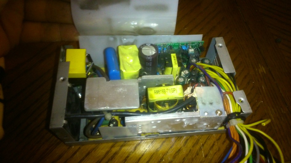
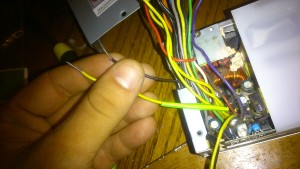
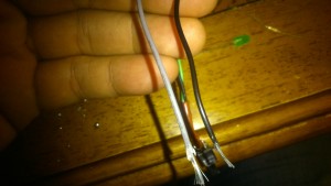
Once you have chosen a suitable power supply for your needs start by cutting off all the plugs and cracking the case open.
Now you’re inside the power supply, be very careful as the capacitors may still have charge.
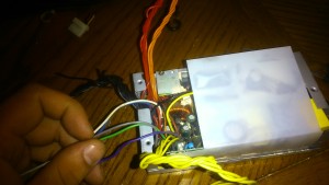
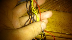
Group the bundle of wires by their colours.
- Yellow = +12v
- Red = +5v
- Orange = +3.3v
- Black = Ground
- Green = Power Supply On
- Grey = PG
- Purple = +5vSB
- White = -5v
- Blue = -12v
Mimicking a load
In order for some modern power supplies to function they require some form of load otherwise they will not power up properly, by using a 10 ohm resister between +12v and ground we can mimic a load.
Select one of the yellow wires and one of the black wires, cut them both fairly short and slip some heat shrink over one of them, solder the 10 ohm resister between these.
Adding a power switch
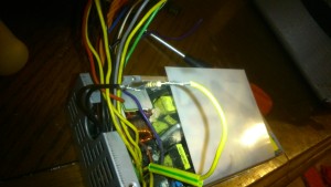
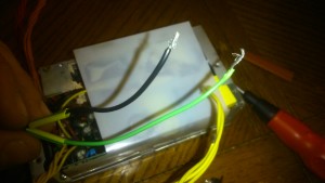
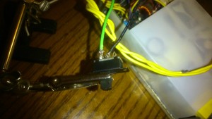
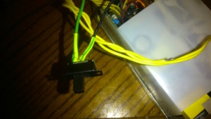
In order to start an ATX power supply the green wire needs to be grounded, if your power supply has a switch on the back already, or you’re not fussed about having a switch then simply solder the green wire to one of the black wires. Otherwise solder the green and one of the black wires to the terminals on a SPST switch (if using a DPDT switch as in the picture, simply ignore the other 4 pins on the switch) using a little heat shrink to avoid any unwanted shorts.
Standby LED
A standby LED has 2 main functions, it will light up whenever the power supply is plugged into the mains, letting you know that it has live mains voltage inside, it will also discharge the capacitors for you once you unplug the power supply, making it safer to work on, due to this the standby LED may stay on for a few seconds after the unit is unplugged.
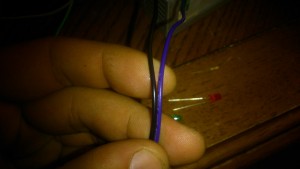
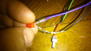
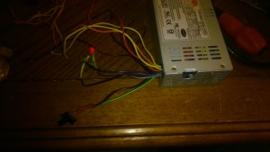
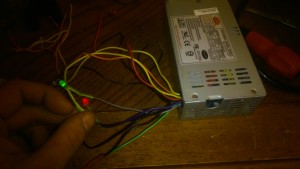
Find the purple wire and select one of the black wires. Solder a 330 ohm resistor onto the black (ground) wire and the shorter leg of the red LED to the other end of the resistor, then solder the longer leg of the LED to the purple wire, using heat shrink will avoid any shorts.
Power LED
A power LED could be added to the 3.3v or 5v rails although ideally the LED should be connected via the grey wire which is designed to send a +5v signal if the power supply is functioning correctly.
Find the grey wire and select one of the black (ground) wires. The power LED is connected in a similar way to the standby LED; solder a 330 ohm resistor onto the black (ground) wire and the shorter leg of the red LED to the other end of the resistor, then solder the longer leg of the LED to the purple wire, using heat shrink will avoid any shorts.
Wires to keep
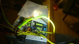
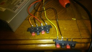
Power supplies can have a lot of wires coming from them consisting of numerous duplicates, in my case I only required 2 of the yellow (+12v) wires, 1 of the red (+5v) wires, 1 of the orange (+3.3v) wires and 4 of the black (ground) wires.
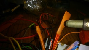
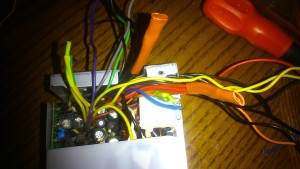
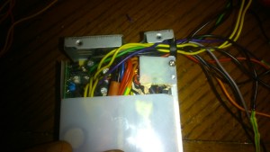
All other wires need to be trimmed down and isolated using heat shrink or electrical tape, if your power supply is large enough to work in you may even be able to disconnect the excess wires from the PCB, with the small form factor power supply I was using I couldn’t even see the PCB let alone get to it!
Testing
Once you are done ensure none of the wires are shorting and re-fit the case. Once you connect the ATX power supply to the mains the red LED should illuminate, flipping the switch should now start the power supply up providing current to your projects as well as illuminating the green power LED.
To be continued…
Leave a Reply